
HOW TO: 1990 Mustang Megasquirt DIY w. pictures


HOW TO: 1990 Mustang Megasquirt DIY w. pictures
I will say this first off. If you arent sure on how to do this, contact Braineack at Miataturbo.net and have him do it for you. Its not that pricey.
So here we go:
DIYAUTOTUNE.com has developed a PNP version for the 90-93 Ford Mustang. Perfect for those with 5.0L engine and harness swaps. Below is a step-by-step guide on building your own.
What to buy:
DIYPNP Ford 60 pin EEC-IV Unassembled Kit
http://www.diyautotune.com/catalog/u...Serial Adapter - There are cheaper cables out there, but this is known good on 98, XP, Vista, and Win7. If you buy a different one, make sure the drivers will work for your OS.
That's it! But here are some other recommendations:
MSPNP and DIYPNP IAT Sensor Kit - Aluminum Bung - This Air Intake Temp Sensor allows you to remove the MAF from the intake path. IIRC, the '93 motor has the factory AIT sensor mounted on the intake manifold, so if you have that motor, you can remove the MAF without purchasing a new sensor. The AIT sensor resides within the MAF otherwise. You will have to mount the bung onto your intake plumbing and you can wire it back through the MAF plug/connector (wire is included for this).
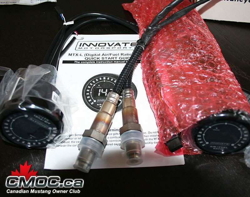
Innovate MTX-L powersports gauge - sensor - controller - 3845 - I personally wouldn't install an EMS without a wideband, I like the one linked. Installing a wideband o2 sensor to use with the MS makes fine tuning your fuel tables & enrichments a lot easier, and you get a real picture of your AFR mixture that the narrowband simply cannot output.
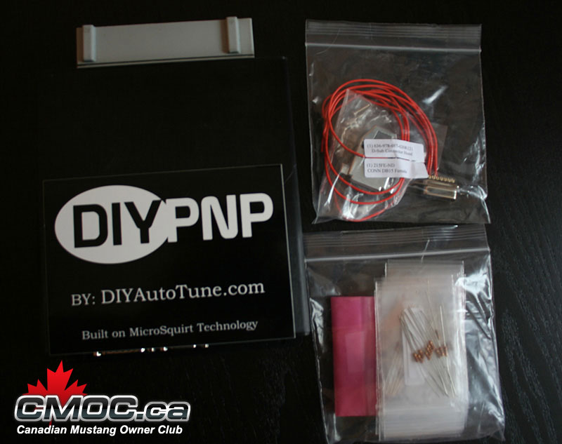
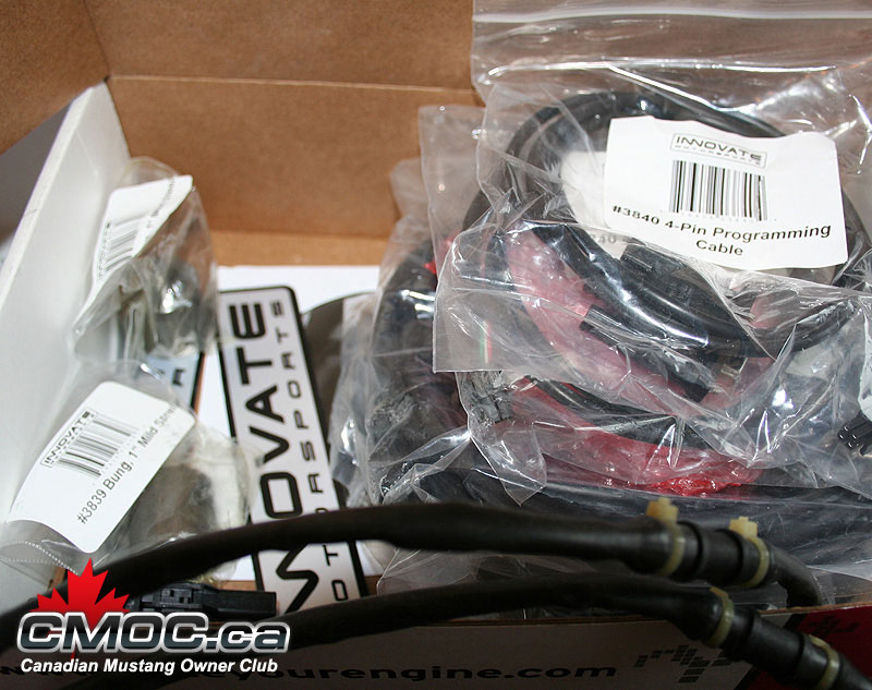
What you get in your package:
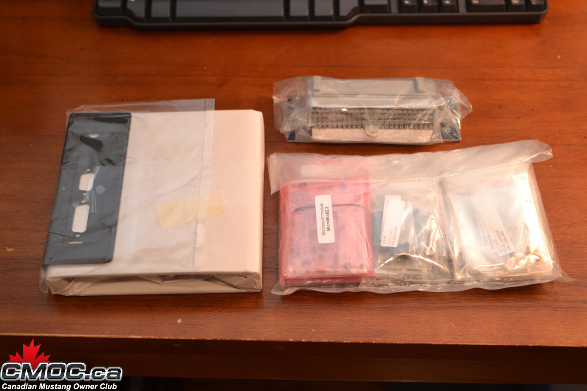
This is the contents of your package. Shown in the case & components you will receive. Each package is clearly marked of its contents.
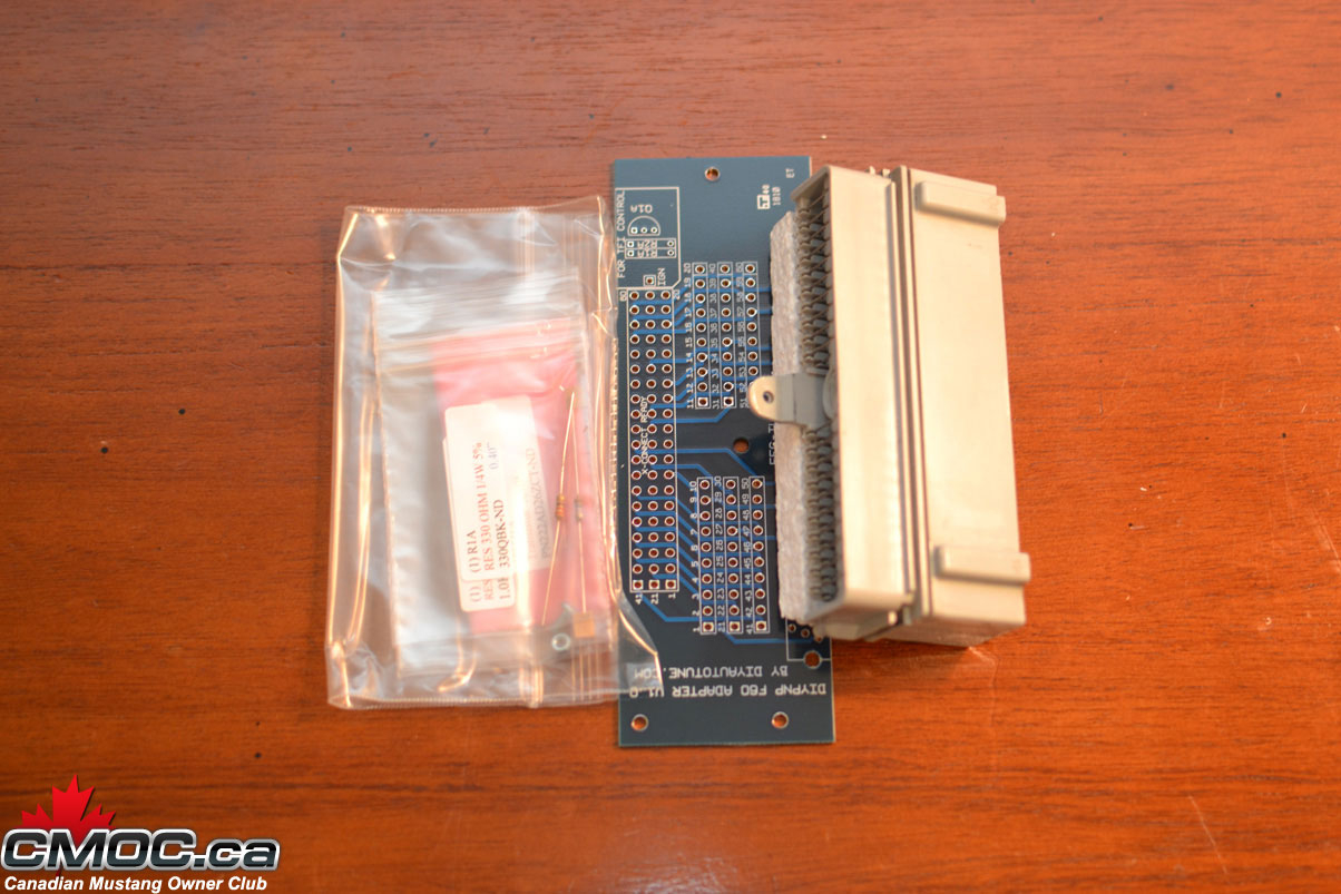

Connector Board - Ford Harness Specific.
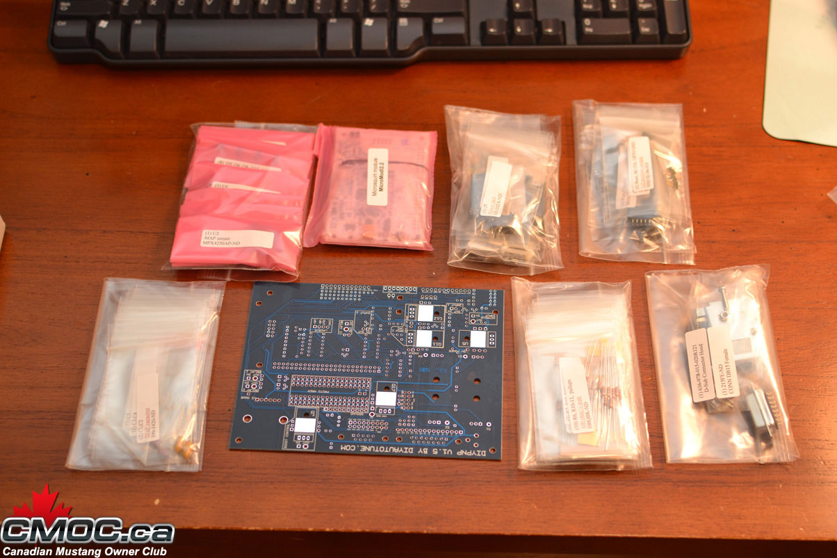
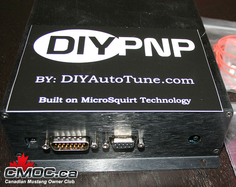
Mainboard and Components.
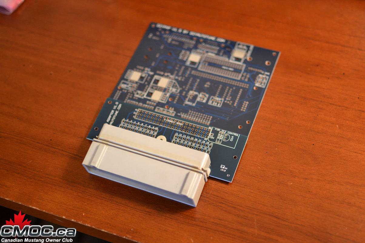
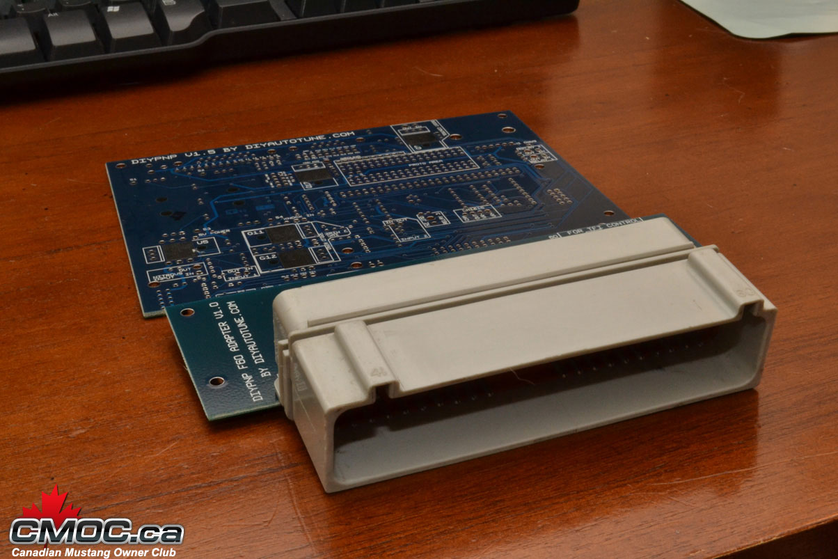
Mainboard and Connector board aligned.
Tools Needed to Assemble:
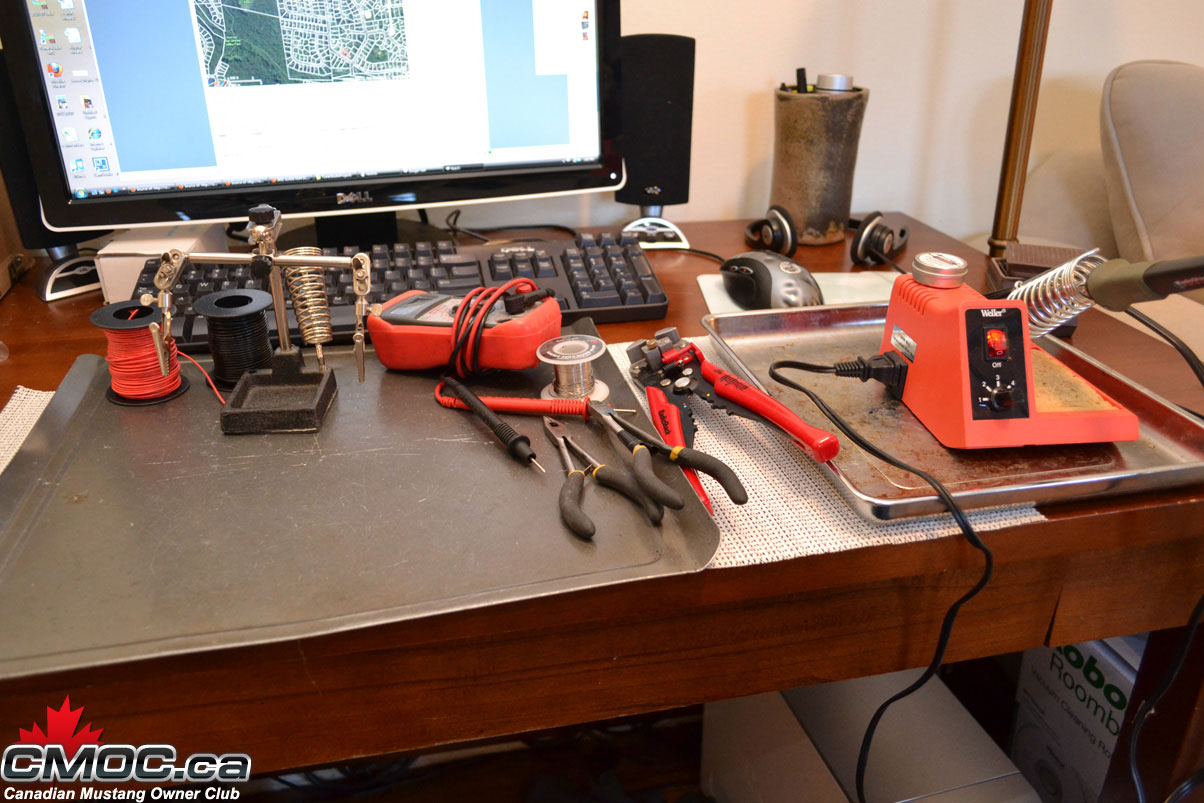
Soldering Iron. Pictured is my trusty $7 40-watt Radio Shack unit plugged into a $30 Weller station to control the temps. Make sure to use a new clean/sharp tip.
Solder. I use 0.030" Resin-Core 60/40.
Wire cutters & Strippers.
Small Pliers. Handy to hold components.
22awg Solid Copper Wire (Red Spool)
22awg Stranded Copper Wire (Black Spool, unused today)
"Helping-Hands". This little guy helps hold the DIYPNP at a good angle when populating components. You can see how I use it below.
All these tools were purchased at my local Radio Shack.
Note: The multi-meter pictured was unused in this assembly, it's just nice to have one handy in case of troubleshooting.
Main Assembly:
Please review the official assembly documentation here: http://www.diyautotune.com/diypnp/do..._assembly.html
Not everything is required to be populated in order to run the MS on your 5.0L. You can chose to install it all, or just install what I do below.
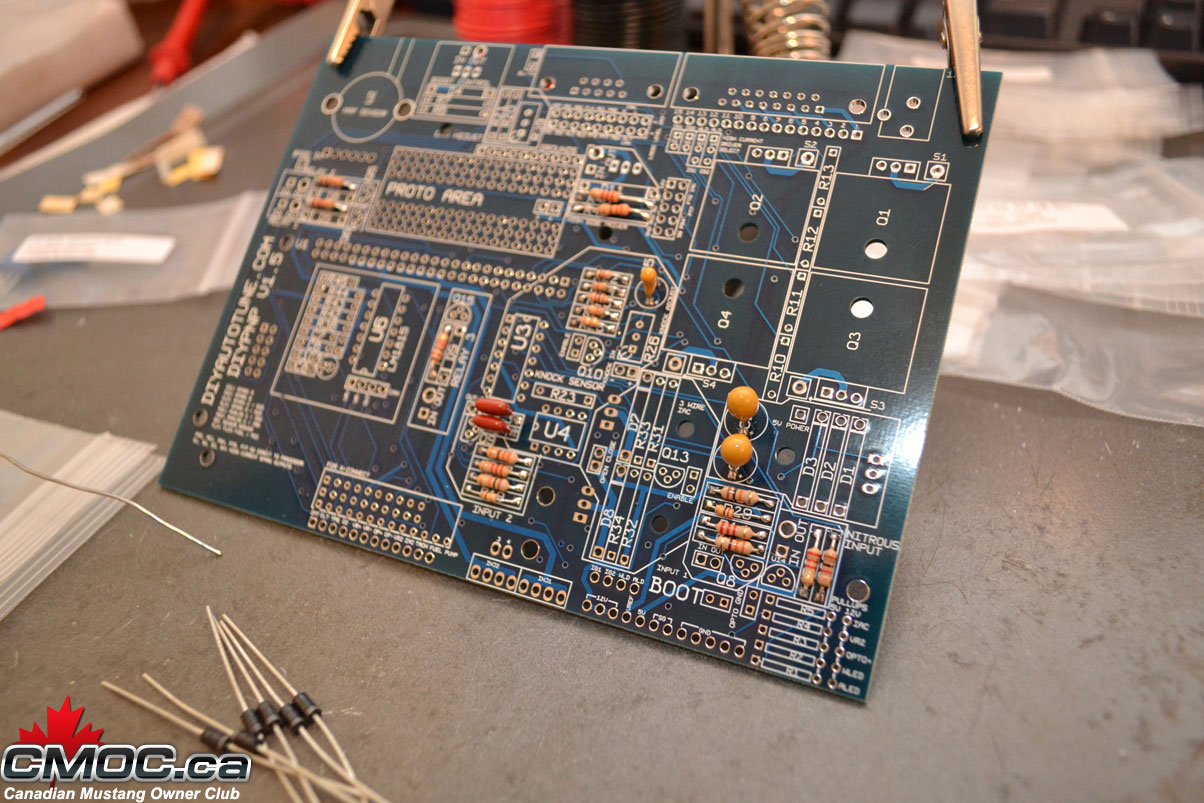
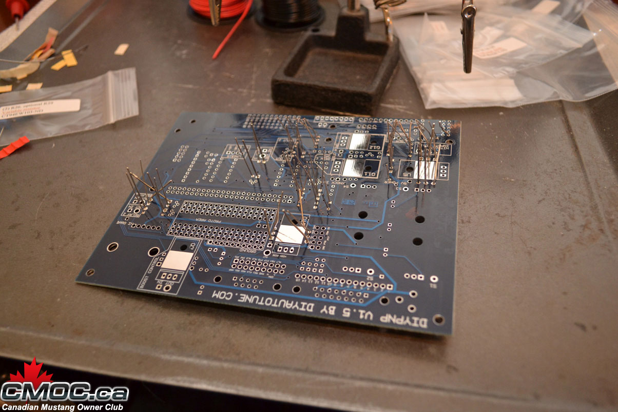
I like to start with the resistors. Setting up the Mainboard on the helping hands, I populate all resistors I chose to install.
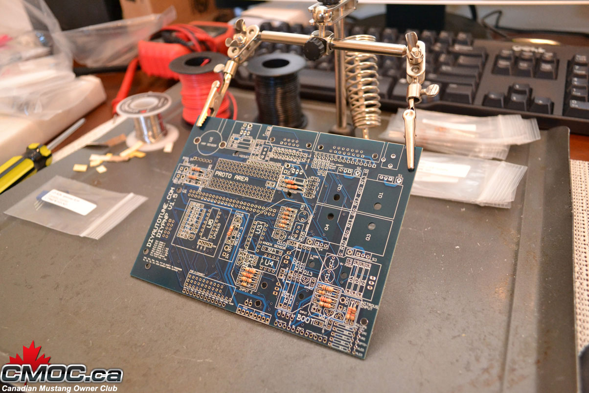
Nothing special about it, simply bend the legs into a "U" and place them into the designated holes.
Once all resistors are populated, I then go through and solder them in place. I do this on the top of the board, holding the solder in my left hand I place the solder against the leg of the resistor right at the hole the component is residing in. Then I bring in the hot iron with my right hand and "melt" the solder into the hole.
Just like this:
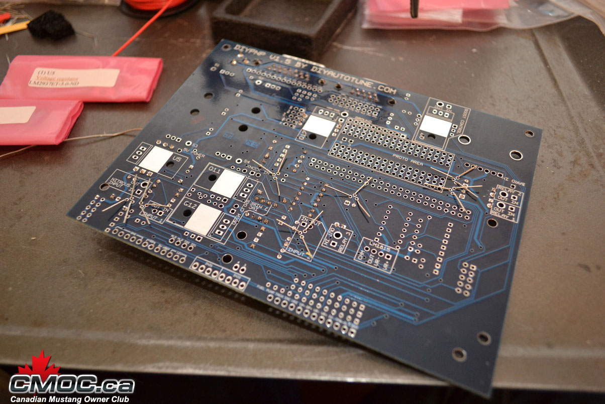
Just happening to be doing it on the topside for these. You can bend the leads back so you can flip the board over and do them from the backside, but I find it takes extra time without benefit.
and the result should look like this:
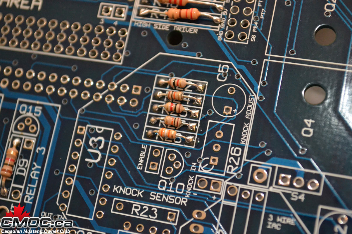
For more information on how to solder components, please review the Google machine.
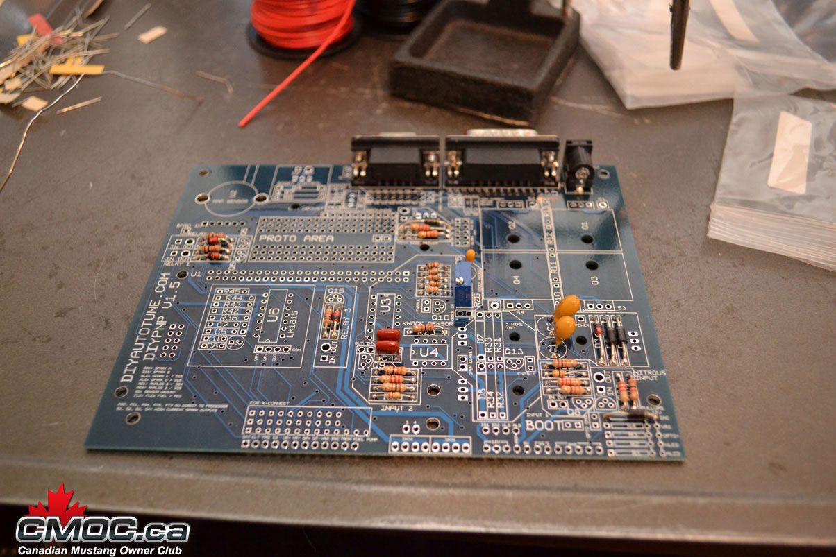
Next I populate the capacitors as shown, please note that three of them are polarity specific. The longer leg goes into the hole stamped with a "+":
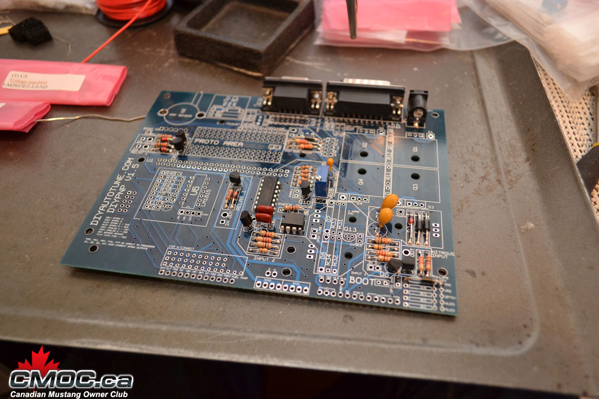
then the diodes, banded end is labeled on the board with a thick white line:
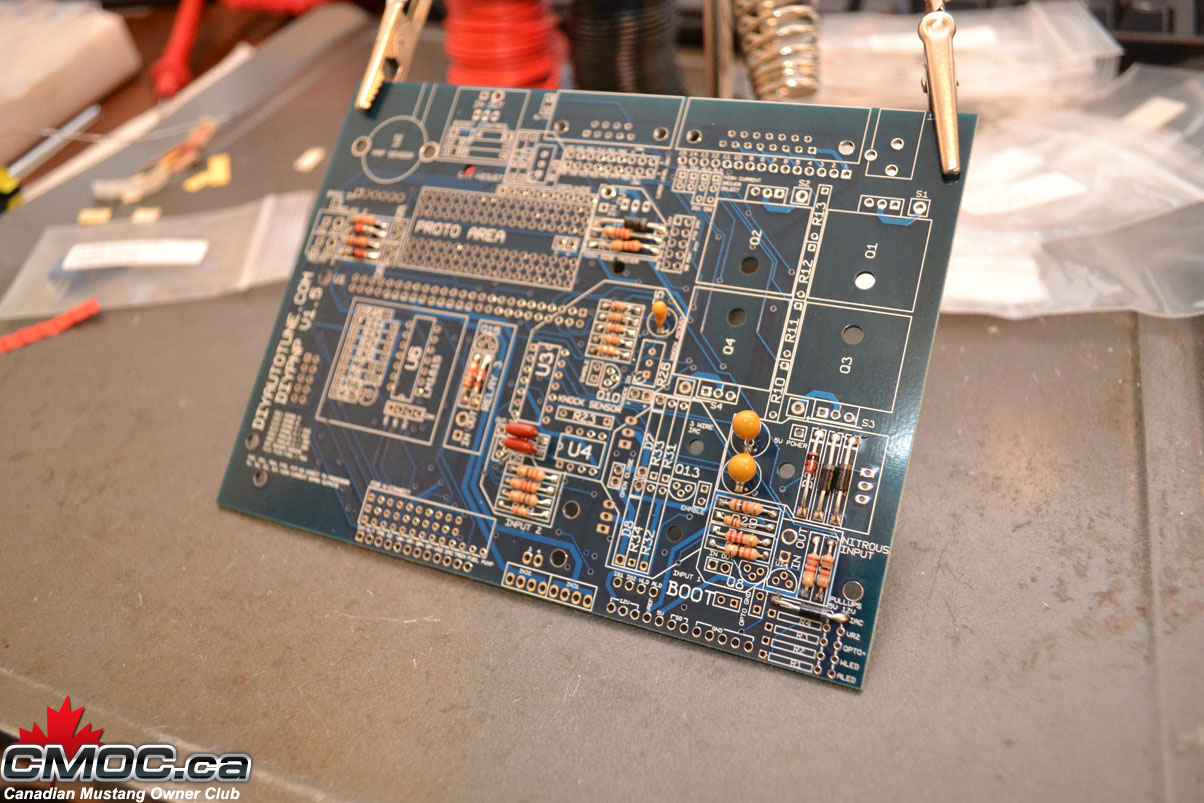
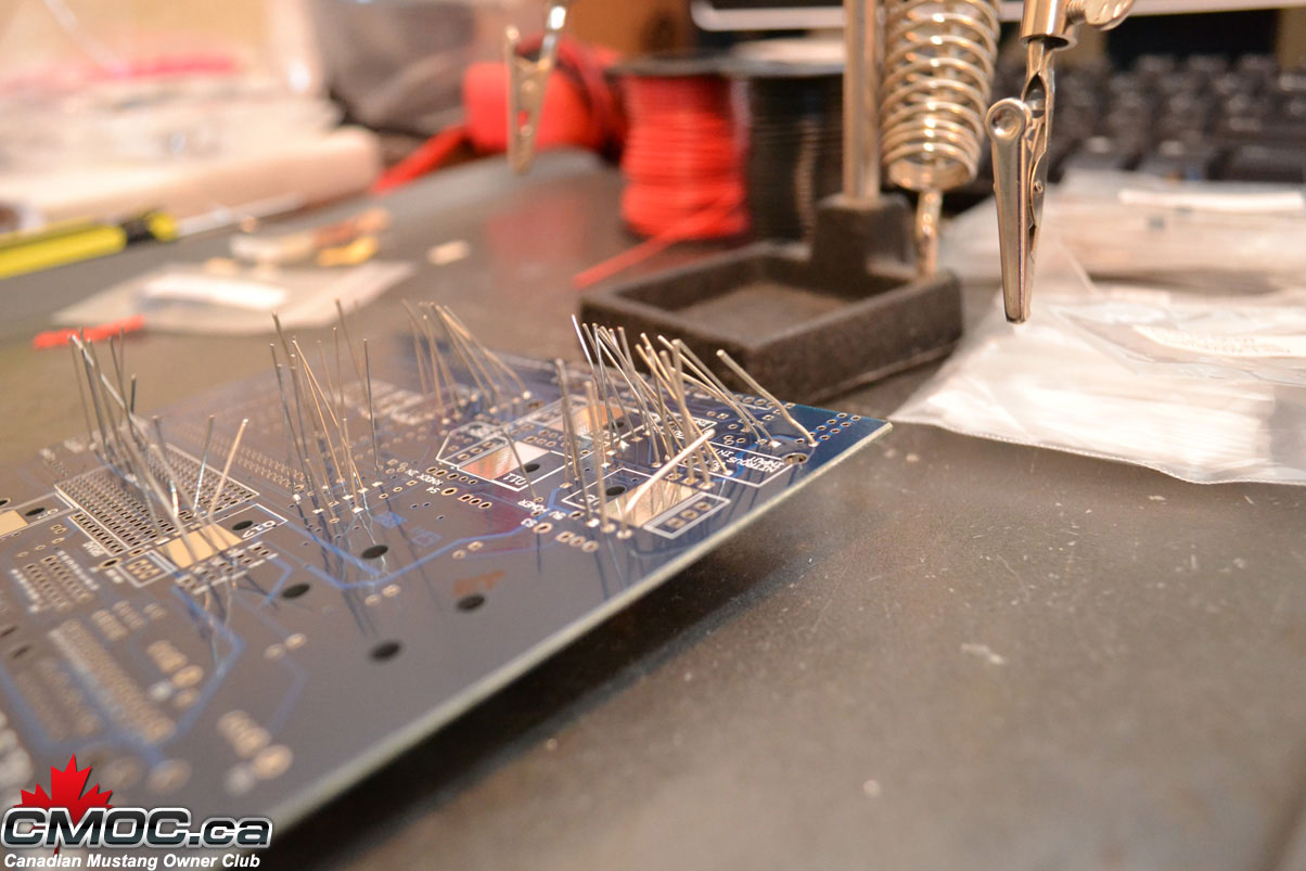
At this point I like to remove the MS from the helping hands and cut off all the legs.
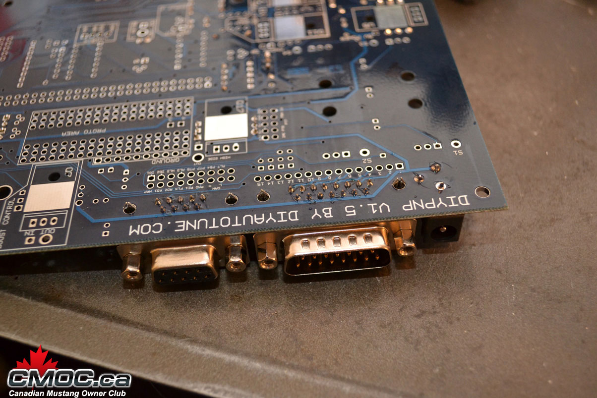
Then you can go ahead and solder in the DB15, DB9, and power input. Place them in and solder from below.
You can also toss now install the pot-resistor for the knock circuit if you're building it:
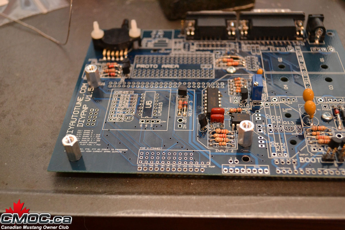
Time to fit the knock sensor dirvers and transistors for the input and relay circuits:
You need to squeeze the legs of the drivers inward so they can drop right into the holes, solder one or two legs from above then finish the rest underneath.
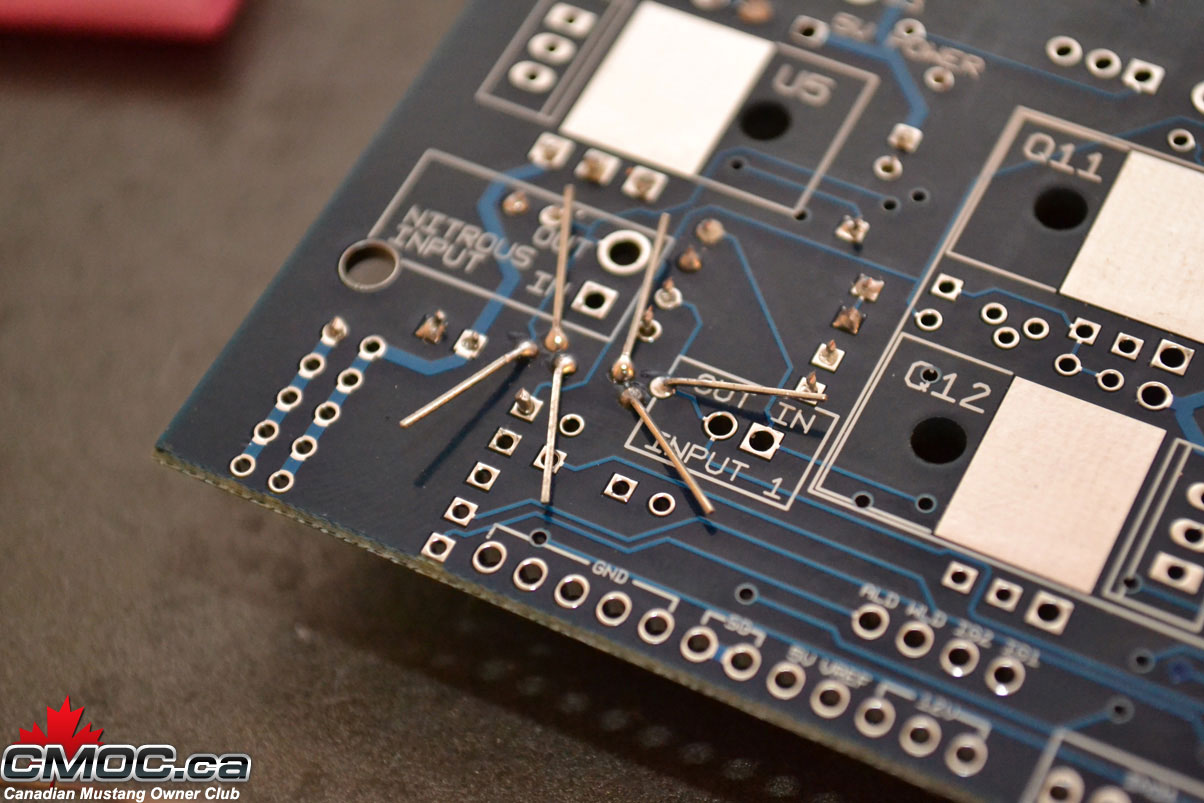
When fitting the transistors, it's good practice to flair the legs on the underside as shown:
Once you start soldering them you'll know why. Be very careful here as it's easy to solder them together. You'll need some de-soldering wire to pull all the solder off.
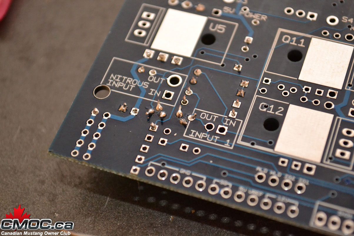
You should be able to make nice clean, individual joints:
then cut off the excess:
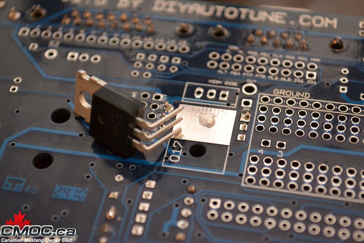
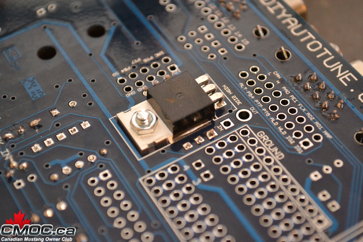
You can now mount the 5v regulator, EBC, and High Side Driver component. Use a small dollop of the heat sink compound on the heatsink area. Here is where the pliers come in handy, Bend the legs so the component can fit right in. Then secure it with the supplied metal screw and nut. Go back and finish soldering once they are all in place.
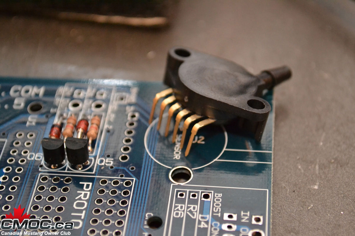
do the same with the MAP sensor, use the two white plastic nuts and bolts:
That's it for the components, onward to the CPU.
Install the stand offs with the provided screws as shown:
Then push together the headers and place them as shown:
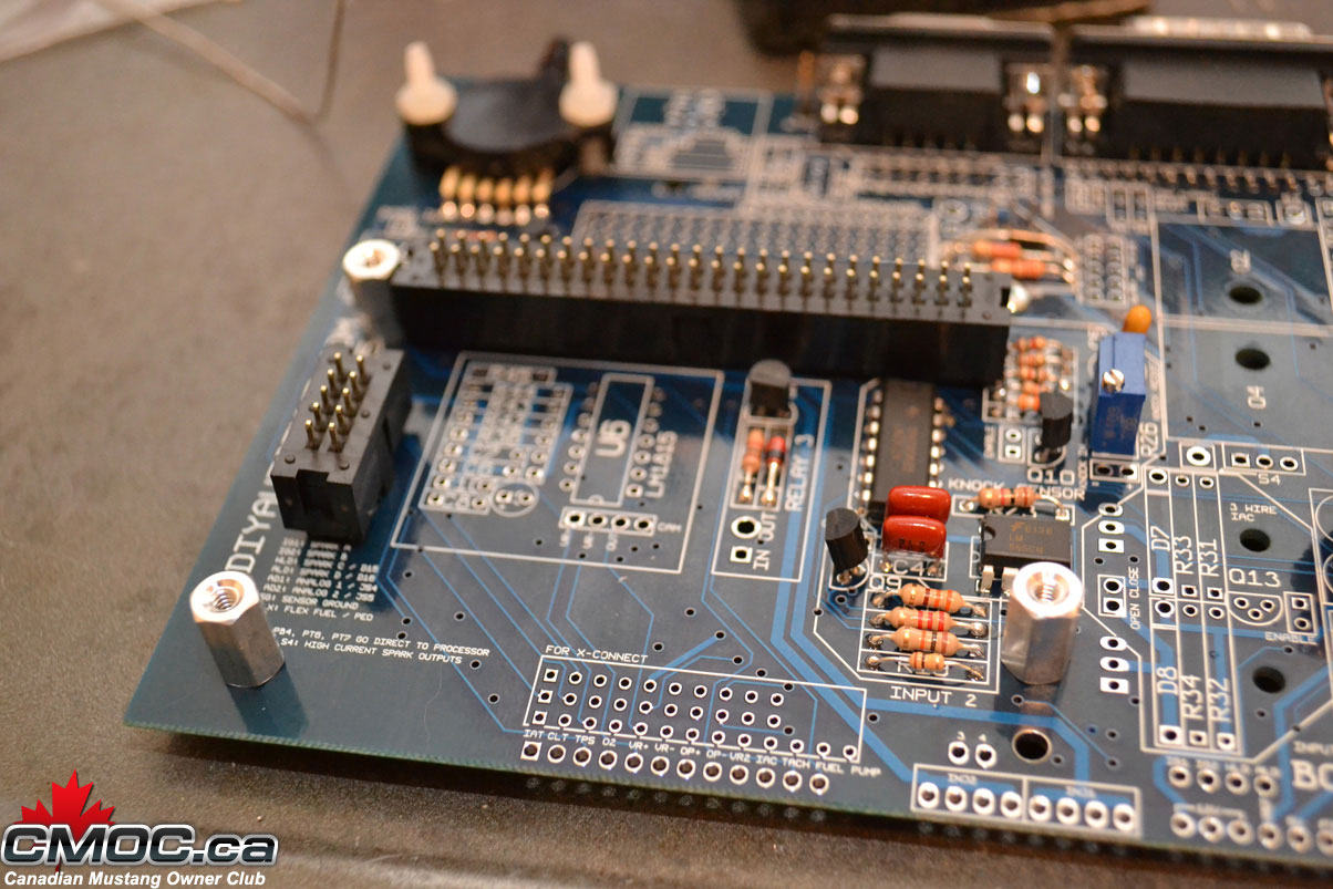
Make sure they sit flush and the tab is pointed inward and the little arrow printed on them is pointing up.
Place the Microsquirt onto, lining up the holes, then screw it in place.
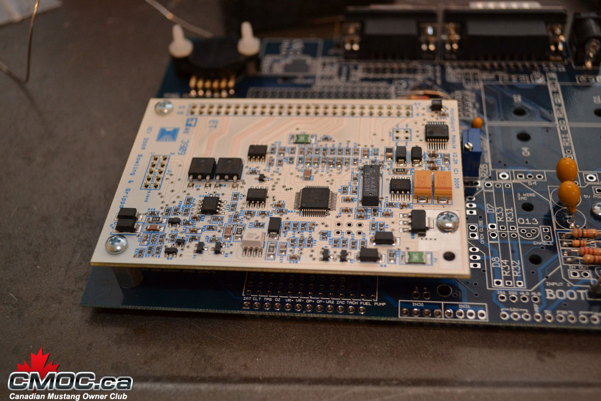
Solder all the joints:
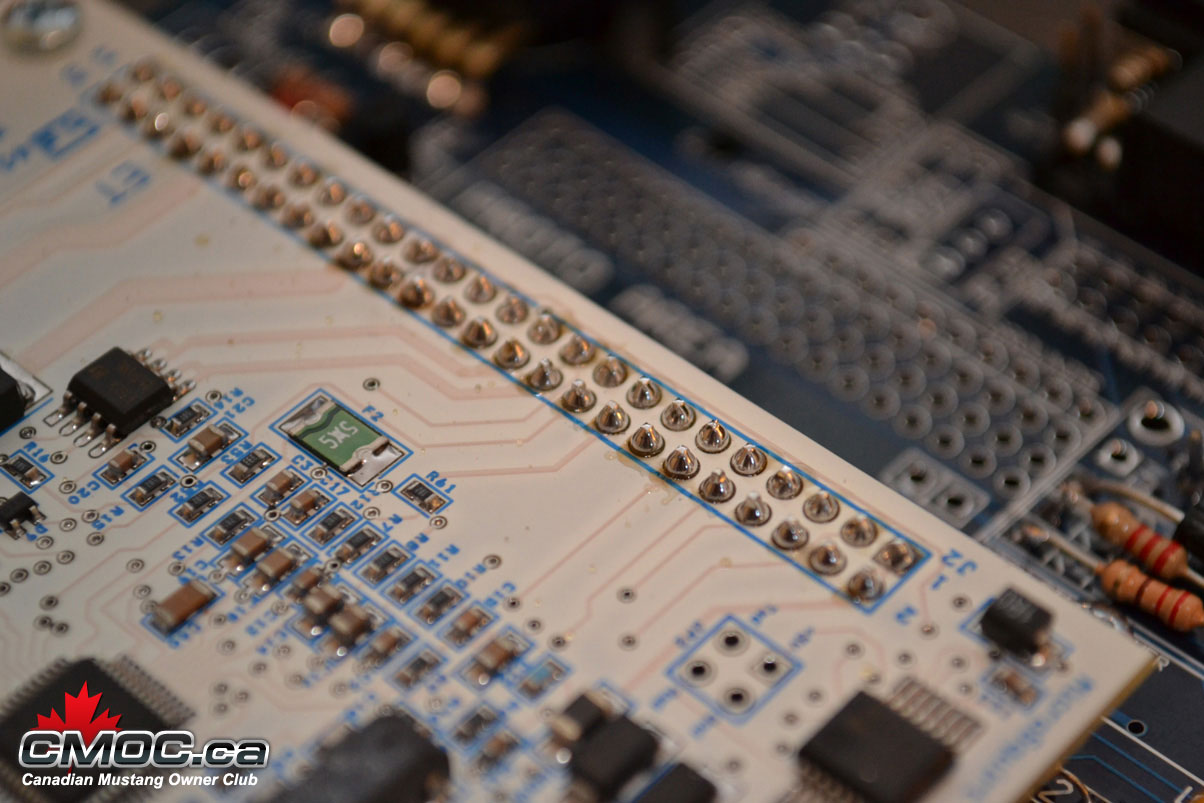
Don't forget the headers on the bottom of the mainboard.
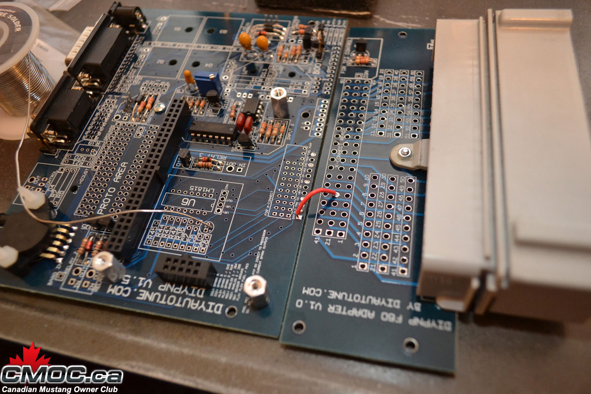
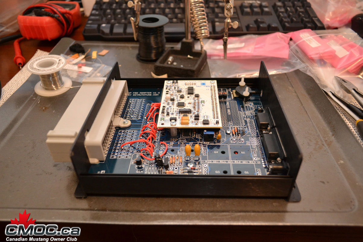
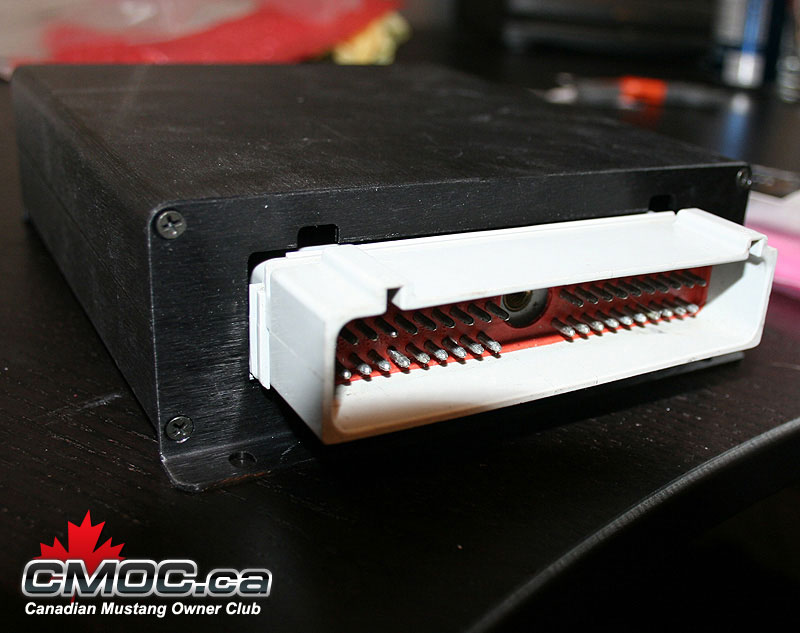
At this point it's time to assemble and connect the connector board. this is the key in how the DIYPNP cleverly is converted into an application specific ECU. Install the connector onto the board, screw it in place carefully, then solder all joints. Populate the small circuit on the board at this point as well.
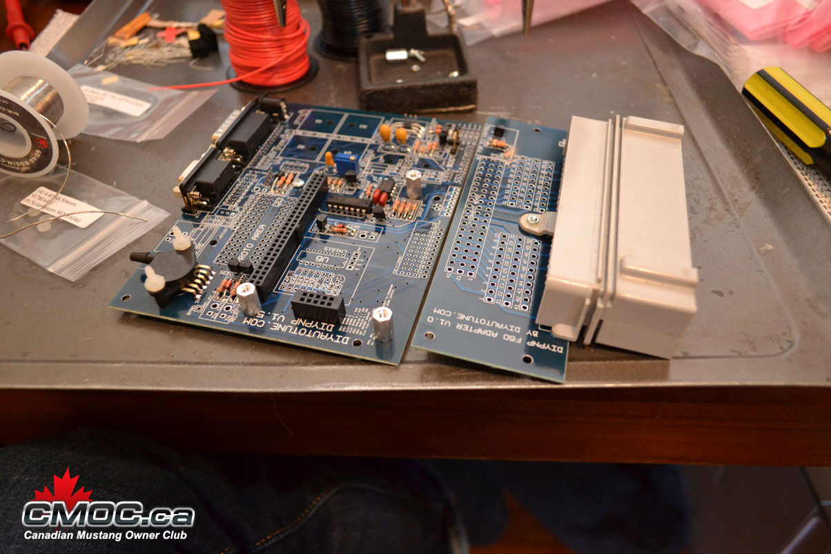
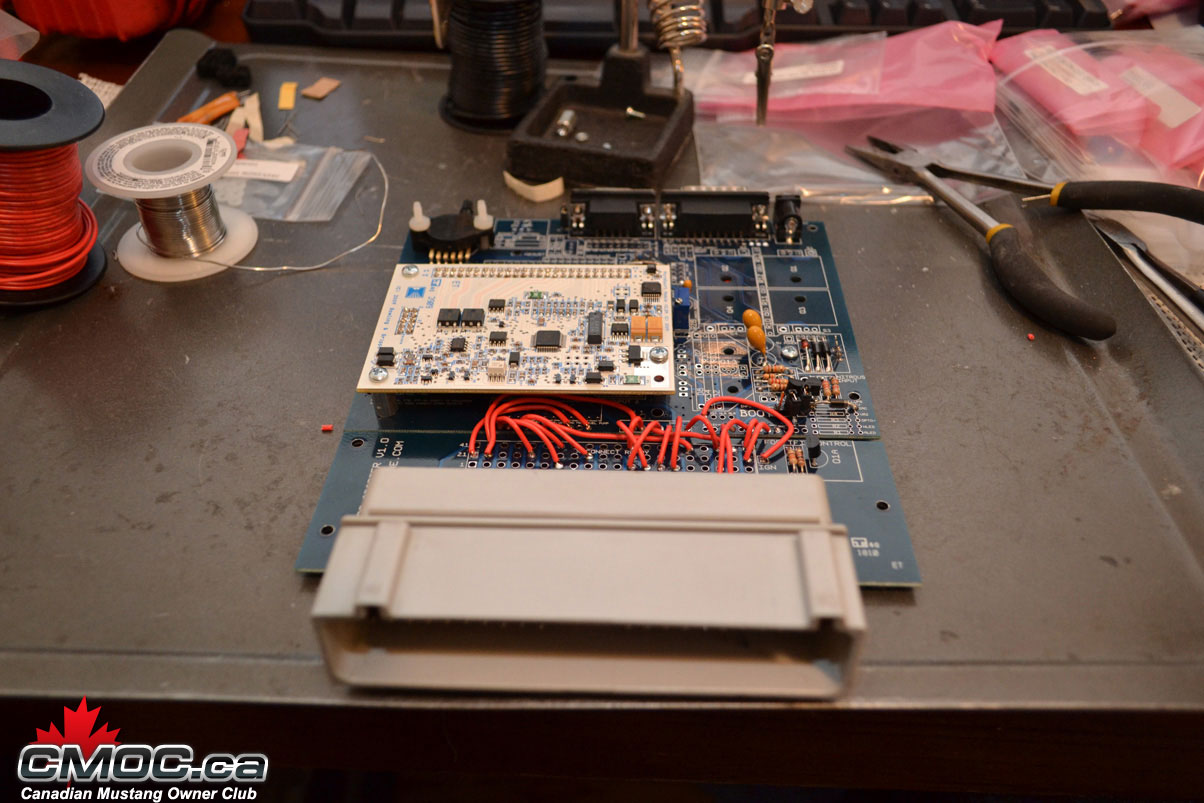
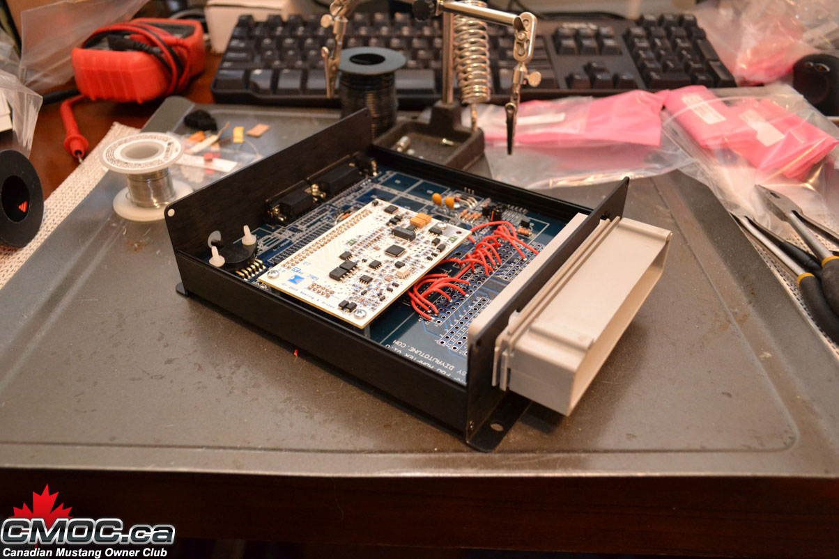
Once you are ready, line it with the mainboard and we can start connecting the two:
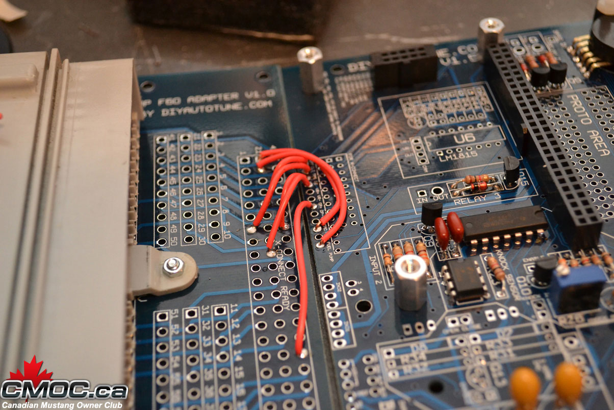
You need to log onto Diyautotune.com's website and follow these directions for the pinouts: http://www.diyautotune.com/diypnp/ap...93-5_0-mt.html
It goes left to right, hole by hole, showing you where to connect the mainboard to the connector board.
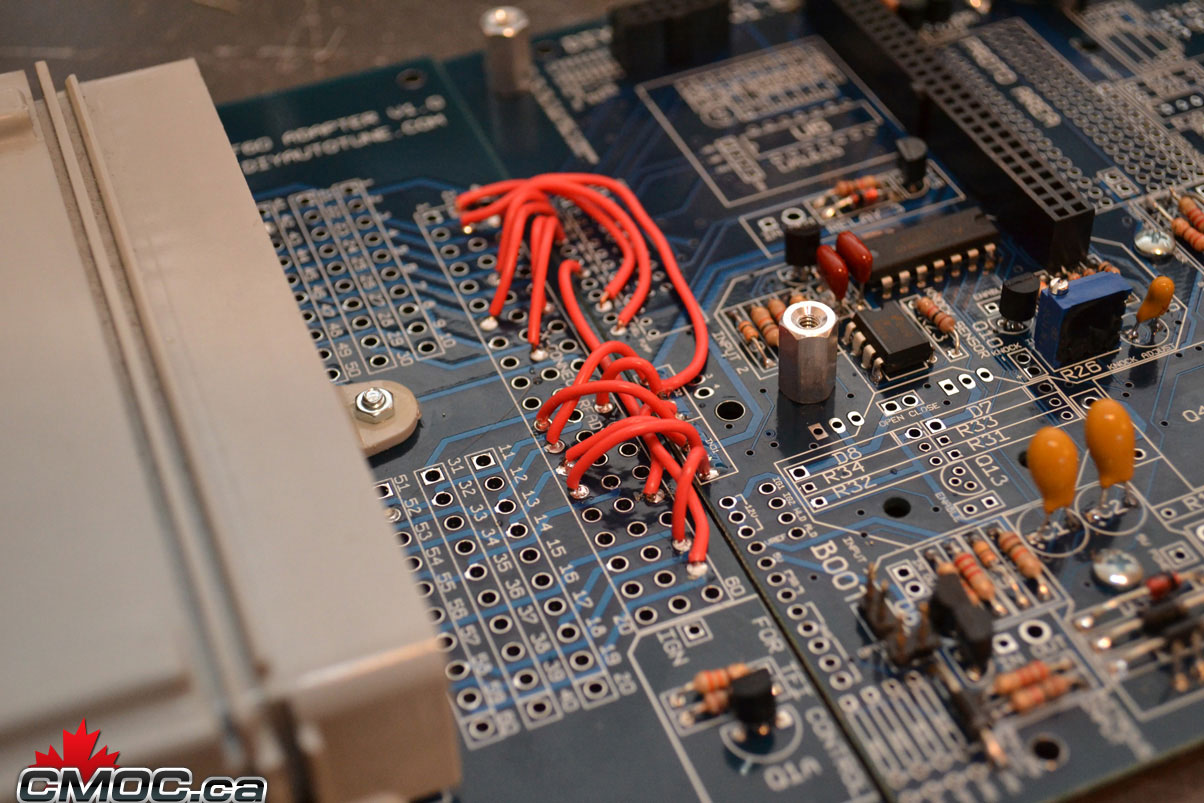
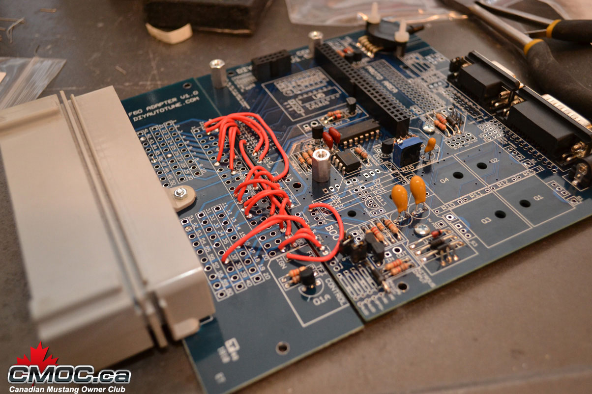
and done.
At this point you are done with the assembly. You can go further and populate other features of the board. You can use the relay circuits to drive things like fans and switches, the EBC driver, Water Injection, Clutch Input, etc.
If you need help at this point, please contact me and I can help you.
A great thing to do now is populate the inputs/outputs for your DB15 connector. This is a blank canvas for simple wiring to and from your MS.
I like to populate mine like this:
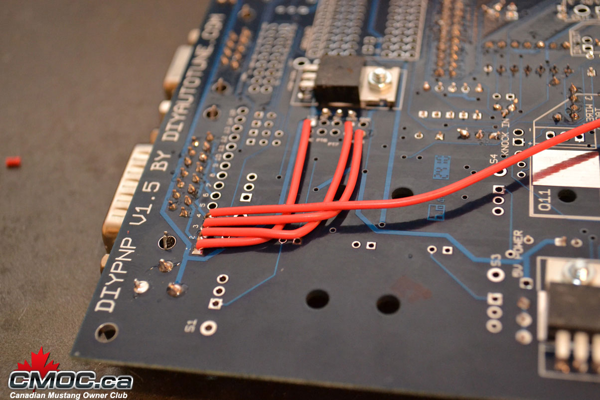
#1 - 12v
#2 - GND
#3 - SG
#4 - O2
This gives me a perfect place to wire up my wideband o2 sensor. I can use the power, ground, sensor ground to power the unit, and then the o2 input on #4 to send the signal into the MS.
Reinstall the CPU, and start to assemble the case.
Slide it into the 2nd slot and attach the end plate with the nuts on the DB9 an dDB15:
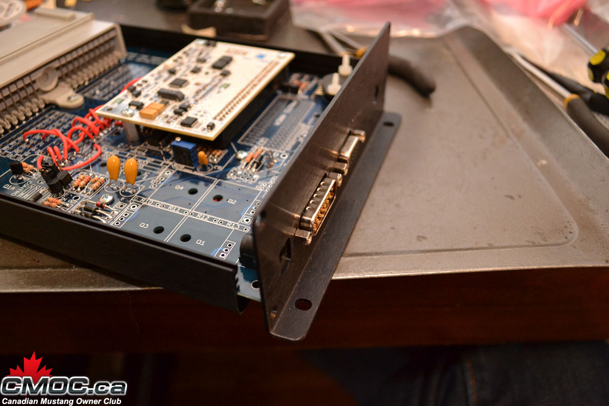
Screw it in place and then slide the second end-plate over the connector and screw it in place as well.
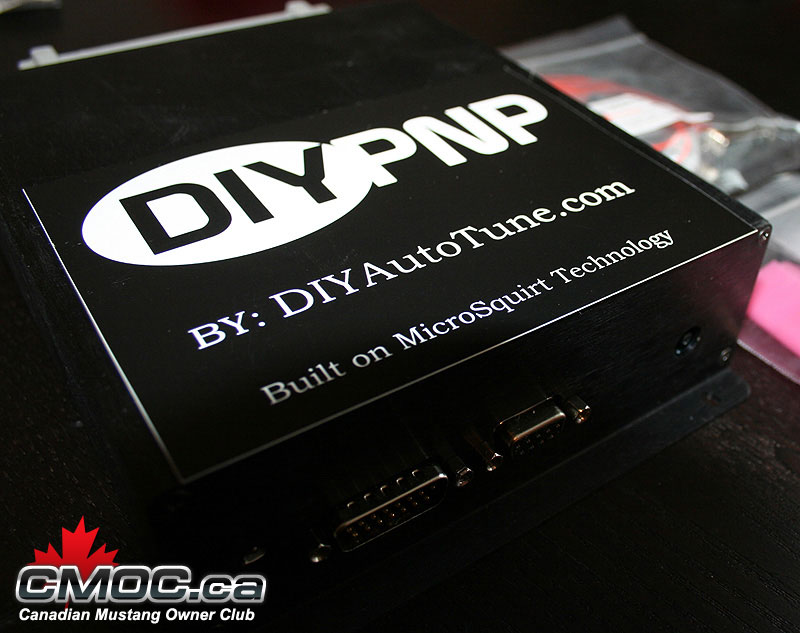
all done:
From start to finish at this point, even taking pictures it took me just over an hour. Time to start loading software, a base tune, and getting it installed.
Well, it has landed, all complete.
Built by Braineack of Miataturbo.net (veteran MS builder). Thanks to Brain for the HOW TO. Very nice!
So here we go:
The DIYPNP board lets you build your own plug and play engine management systems. The core of the DIYPNP kit is a MicroSquirt module that plugs into an expansion 'mainboard' with on board circuits for many features, including direct coil control, boost control, knock control, and several general purpose inputs and outputs. You assemble this board and jumper it to a 'connector board' which includes a connector to plug into your existing wiring harness. Now you no longer have to solder together awkward adapter harnesses, or hack up a factory ECU case to get a build-it-yourself, plug and play MegaSquirt ECU.
What to buy:
DIYPNP Ford 60 pin EEC-IV Unassembled Kit
http://www.diyautotune.com/catalog/u...Serial Adapter - There are cheaper cables out there, but this is known good on 98, XP, Vista, and Win7. If you buy a different one, make sure the drivers will work for your OS.
That's it! But here are some other recommendations:
MSPNP and DIYPNP IAT Sensor Kit - Aluminum Bung - This Air Intake Temp Sensor allows you to remove the MAF from the intake path. IIRC, the '93 motor has the factory AIT sensor mounted on the intake manifold, so if you have that motor, you can remove the MAF without purchasing a new sensor. The AIT sensor resides within the MAF otherwise. You will have to mount the bung onto your intake plumbing and you can wire it back through the MAF plug/connector (wire is included for this).
Innovate MTX-L powersports gauge - sensor - controller - 3845 - I personally wouldn't install an EMS without a wideband, I like the one linked. Installing a wideband o2 sensor to use with the MS makes fine tuning your fuel tables & enrichments a lot easier, and you get a real picture of your AFR mixture that the narrowband simply cannot output.
What you get in your package:
This is the contents of your package. Shown in the case & components you will receive. Each package is clearly marked of its contents.
Connector Board - Ford Harness Specific.
Mainboard and Components.
Mainboard and Connector board aligned.
Tools Needed to Assemble:
Soldering Iron. Pictured is my trusty $7 40-watt Radio Shack unit plugged into a $30 Weller station to control the temps. Make sure to use a new clean/sharp tip.
Solder. I use 0.030" Resin-Core 60/40.
Wire cutters & Strippers.
Small Pliers. Handy to hold components.
22awg Solid Copper Wire (Red Spool)
22awg Stranded Copper Wire (Black Spool, unused today)
"Helping-Hands". This little guy helps hold the DIYPNP at a good angle when populating components. You can see how I use it below.
All these tools were purchased at my local Radio Shack.
Note: The multi-meter pictured was unused in this assembly, it's just nice to have one handy in case of troubleshooting.
Main Assembly:
Please review the official assembly documentation here: http://www.diyautotune.com/diypnp/do..._assembly.html
Not everything is required to be populated in order to run the MS on your 5.0L. You can chose to install it all, or just install what I do below.
I like to start with the resistors. Setting up the Mainboard on the helping hands, I populate all resistors I chose to install.
Nothing special about it, simply bend the legs into a "U" and place them into the designated holes.
Once all resistors are populated, I then go through and solder them in place. I do this on the top of the board, holding the solder in my left hand I place the solder against the leg of the resistor right at the hole the component is residing in. Then I bring in the hot iron with my right hand and "melt" the solder into the hole.
Just like this:
Just happening to be doing it on the topside for these. You can bend the leads back so you can flip the board over and do them from the backside, but I find it takes extra time without benefit.
and the result should look like this:
For more information on how to solder components, please review the Google machine.
Next I populate the capacitors as shown, please note that three of them are polarity specific. The longer leg goes into the hole stamped with a "+":
then the diodes, banded end is labeled on the board with a thick white line:
At this point I like to remove the MS from the helping hands and cut off all the legs.
Then you can go ahead and solder in the DB15, DB9, and power input. Place them in and solder from below.
You can also toss now install the pot-resistor for the knock circuit if you're building it:
Time to fit the knock sensor dirvers and transistors for the input and relay circuits:
You need to squeeze the legs of the drivers inward so they can drop right into the holes, solder one or two legs from above then finish the rest underneath.
When fitting the transistors, it's good practice to flair the legs on the underside as shown:
Once you start soldering them you'll know why. Be very careful here as it's easy to solder them together. You'll need some de-soldering wire to pull all the solder off.
You should be able to make nice clean, individual joints:
then cut off the excess:
You can now mount the 5v regulator, EBC, and High Side Driver component. Use a small dollop of the heat sink compound on the heatsink area. Here is where the pliers come in handy, Bend the legs so the component can fit right in. Then secure it with the supplied metal screw and nut. Go back and finish soldering once they are all in place.
do the same with the MAP sensor, use the two white plastic nuts and bolts:
That's it for the components, onward to the CPU.
Install the stand offs with the provided screws as shown:
Then push together the headers and place them as shown:
Make sure they sit flush and the tab is pointed inward and the little arrow printed on them is pointing up.
Place the Microsquirt onto, lining up the holes, then screw it in place.
Solder all the joints:
Don't forget the headers on the bottom of the mainboard.
At this point it's time to assemble and connect the connector board. this is the key in how the DIYPNP cleverly is converted into an application specific ECU. Install the connector onto the board, screw it in place carefully, then solder all joints. Populate the small circuit on the board at this point as well.
Once you are ready, line it with the mainboard and we can start connecting the two:
You need to log onto Diyautotune.com's website and follow these directions for the pinouts: http://www.diyautotune.com/diypnp/ap...93-5_0-mt.html
It goes left to right, hole by hole, showing you where to connect the mainboard to the connector board.
and done.
At this point you are done with the assembly. You can go further and populate other features of the board. You can use the relay circuits to drive things like fans and switches, the EBC driver, Water Injection, Clutch Input, etc.
If you need help at this point, please contact me and I can help you.
A great thing to do now is populate the inputs/outputs for your DB15 connector. This is a blank canvas for simple wiring to and from your MS.
I like to populate mine like this:
#1 - 12v
#2 - GND
#3 - SG
#4 - O2
This gives me a perfect place to wire up my wideband o2 sensor. I can use the power, ground, sensor ground to power the unit, and then the o2 input on #4 to send the signal into the MS.
Reinstall the CPU, and start to assemble the case.
Slide it into the 2nd slot and attach the end plate with the nuts on the DB9 an dDB15:
Screw it in place and then slide the second end-plate over the connector and screw it in place as well.
all done:
From start to finish at this point, even taking pictures it took me just over an hour. Time to start loading software, a base tune, and getting it installed.
Well, it has landed, all complete.
Built by Braineack of Miataturbo.net (veteran MS builder). Thanks to Brain for the HOW TO. Very nice!
Last edited by 2tone; Mar 10, 2011 at 01:09 PM.


Thread
Thread Starter
Forum
Replies
Last Post
Matt Cramer
DIYAutoTune - Ford Mustang Accessories
1
Aug 28, 2012 01:48 PM
Matt Cramer
DIYAutoTune - Ford Mustang Accessories
3
Jun 15, 2012 05:40 PM
Matt Cramer
DIYAutoTune - Ford Mustang Accessories
6
Jan 30, 2012 04:26 PM


